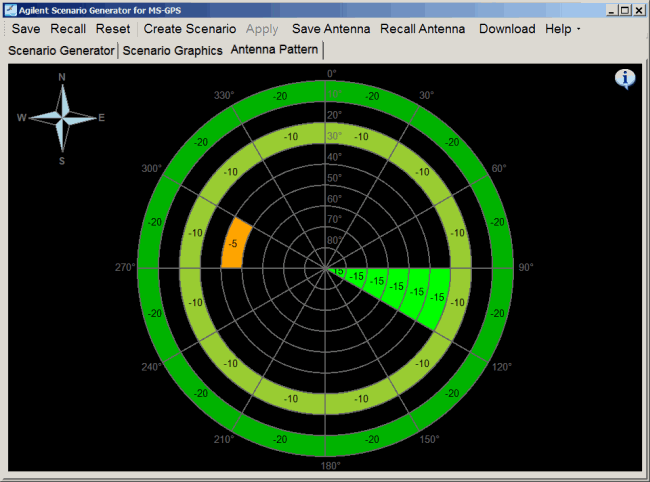
Antenna Pattern
The  Antenna Pattern
tab, while always visible, is applicable with only the Static Scenario Type with Antenna
Pattern set to On. When a Static scenario is created with an antenna
pattern, the software embeds the antenna pattern as part of the generated
scenario file. In addition, the software enables the saving of the antenna
pattern separately for use with a new scenario or as a starting point
for a new antenna pattern to use with a new scenario..
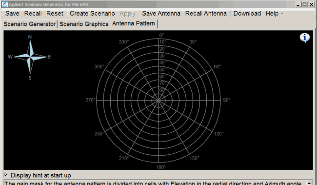
The purpose of the antenna pattern is to specify a region or regions
within the view of the receiver antenna where the satellite power is lowered
by the gain mask value (a power offset). When a satellite enters a gain
masked region, the satellite power is lowered. If the set satellite power
level is already low, there is the possibility that when the gain mask
offset is applied, the satellite may become undetectable by the receiver.
For example, if the set satellite power level is -100 dBm and the gain
mask region is set to -60 dB, when the satellite enters the gain masked
region, its power level drops to -160 dBm. Dependent upon the receiver
sensitivity, this power level may be too low to be detected. Even when
a satellite cannot be detected by the receiver because of the power level,
the signal generator still includes all of the satellites in its list
of visible satellites. To detect the satellite, you will either have to
increase the satellite power or edit the gain mask value of the antenna
pattern to a setting that enables the satellite detection. If the antenna
pattern is edited, a new scenario needs to be created to capture the antenna
pattern changes.
Orientation Reference
The compass on the top-left
corner provides the orientation reference for the sky-view gain mask.
Configure Antenna Pattern
Configure the Antenna
Pattern by filling the cells in the sky-view with proper gain values to
form a gain mask. The gain mask for the antenna pattern is divided into
cells with elevation in the radial direction and azimuth angle increasing
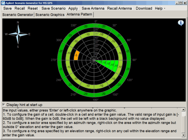
in the clockwise direction. Configure the antenna pattern using the methods
below. To accept the input values, either press Enter or click anywhere
on the graphic.
-
To
configure the gain of a cell, double-click in a cell and enter the gain
value.
The valid range of input gain is [-60 dB to 0 dB]. When the gain is
0 dB, the cell will remain black with no value displayed.
-
To
configure a sector area specified by an azimuth range, right-click in
the area within the azimuth range but outside 0° elevation and enter the
gain value.
-
To
configure a ring area specified by an elevation range, right-click on
any cells within the elevation range and enter the gain value.
-
To
hide the hint information (the same information shown in the previous
bullets) at the bottom of the window and expand the antenna pattern graphic,
 click
the information icon
Antenna Pattern Rotation
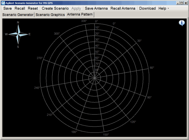
The default antenna pattern
with 0° azimuth pointing to North is called the base pattern. To make
the pattern rotate from the base pattern with a specified angle, change
Azimuth Rotation in the Scenario Generator tab. Antenna Pattern
rotation is useful for modeling receiver antenna that will change its
orientation in different test environments.
The figure below shows
an antenna pattern with 20° of rotation.
Save/Recall Antenna Pattern
The Save
Antenna and Recall Antenna  buttons
on the tool bar allow you to save an already configured antenna pattern
to a file, or to recall a previous pattern from a file. This includes
antenna patterns created with Option 422 software. The saved and recalled
antenna pattern is for use with only a new scenario.
The  antenna pattern file
is in *.csv format with the header in the first line like this:
Sample antenna pattern file

AGILENT_ANTENNA_PATTERN,
version number, file name, elevation resolution value, azimuth resolution
value, azimuth rotation value, generation date time, Keysight Technologies
The rows and columns
represent the azimuth and elevation blocks, respectively. For example,
the first data column represents the gain values for elevation [0° - 10°]
across the whole azimuth range. The second data row represents the gain
values for azimuth [30° - 60°] across the whole elevation range. Change
the antenna pattern by editing the cell values.
The antenna pattern is also saved with the
other scenario generation parameters using the Save button. But using
the Save button does not create the separate csv file.
Color Coding
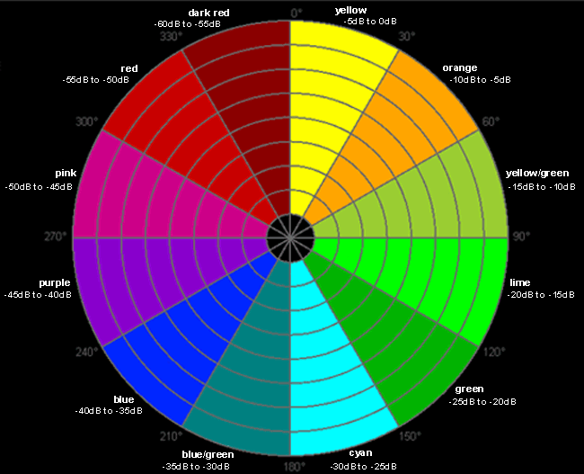
The figure and table below
show the colors used for gain value ranges on the sky-view gain mask.
|
Gain Value Range
|
Cell Color
|
|
-5 dB to 0 dB
|
Yellow
|
|
-10 dB to -5 dB
|
Orange
|
|
-15 dB to -10 dB
|
Yellow/Green
|
|
-20 dB to -15 dB
|
Lime
|
|
-25 dB to -20 dB
|
Green
|
|
-30 dB to -25 dB
|
Cyan
|
|
-35 dB to -30 dB
|
Blue/Green
|
|
-40 dB to -35 dB
|
Blue
|
|
-45 dB to -40 dB
|
Purple
|
|
-50 dB to -45 dB
|
Pink
|
|
-55 dB to -50 dB
|
Red
|
|
-60 dB to -55 dB
|
Dark Red
|
 Antenna Pattern
tab, while always visible, is applicable with only the Static Scenario Type with Antenna
Pattern set to On. When a Static scenario is created with an antenna
pattern, the software embeds the antenna pattern as part of the generated
scenario file. In addition, the software enables the saving of the antenna
pattern separately for use with a new scenario or as a starting point
for a new antenna pattern to use with a new scenario..
